A quicky on eyepiece projection photography
 |
 |
|
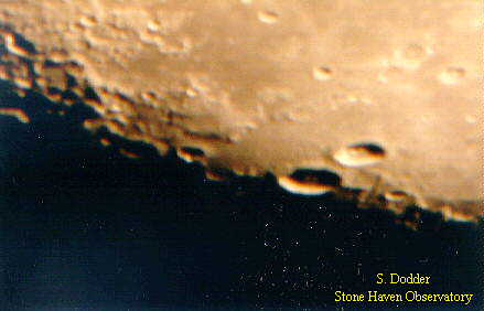
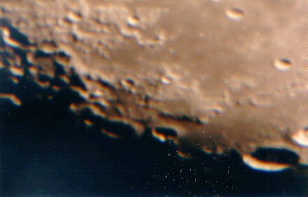
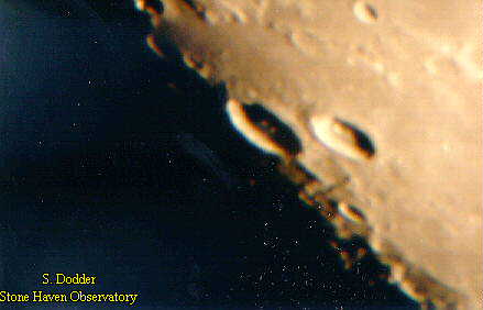
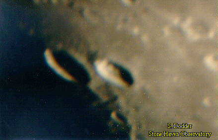
These 4 images illustrate the principle of eyepiece projection astrophotography. They were taken with a C8, 2 eyepieces of 25mm and 10mm, an adjustable telextender from Meade, and a Canon A-1 fitted with a T-ring. The telextender holds one of the eyepieces in such a way as to place it between the telescope and the camera. It's adjustable in that it consists of two telescoping tubes, one inside the other. This allows the operator to change the distance from the back of the telescope to the film plane of the camera, thus changing the effective magnification of the object observed in the telescope. The longer this distance, the greater the magnification. The top two images (Crater 1 and Crater 2) show the range of magnification from minimum to maximum with the 25mm eyepiece installed in the telextender. The bottom two (Crater 3 and Crater 4) show the range with the 10mm installed. In case you haven't noticed, all 4 shots are of the same pair of craters. The image got rotated when I changed eyepieces and forgot to realign the camera in the same orientation as the original 2 images. Oops. The pictures below show the arrangement a little better.
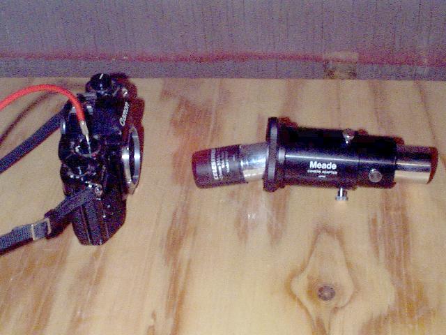
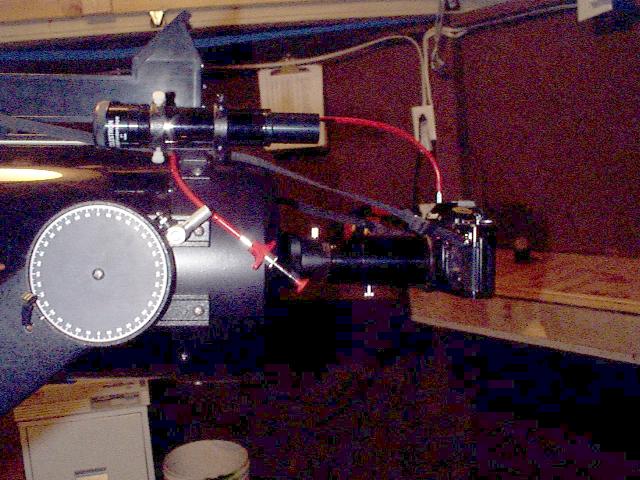
Figure 1 shows the actual pieces of this puzzle. The camera body on the left, with the cable release attached, the eyepiece drawn out of the telextender so you can see it, then the T-ring attached to the telextender tubes. The two screws on the left section allow the tube to be drawn out and secured, the screw on the right section secures the eyepiece inside the telextender. Figure 2 shows the whole thing attached to the back of the C8. (I suppose I should have aligned the components in figure one in the opposite direction, to match the orientation of figure 2, but I didn't think of it til just now. Another oops.) Figure 3 shows a nice drawing of the arrangement.
Copyright 1999, Steve Dodder Webmaster : Steve Dodder Revised: 8/26/10 |