Pierre Schwaar's 8" F/4 Binocular Chair Restoration
Optical Tube Assembly
Pierre has left us, but his legacy lives on in his myriad optical creations. This page will chronical the rebuilding of one of them-his motorized, 8" F/4.2 binocular chair. I happened onto it during one of the first SAC ATM meetings. A lot of Pierre's equipment and supplies were left behind. Some were brought to the meeting for ideas on what to do with it. Someone was suggesting we split the optical tube assemblies into two 8" F/4.2 Dobs to be used as club scopes for newbies. I found this idea abhorent, so I volunteered to take it all home, evaluate its disposition and refurbish it if possible. I had a plan to install it in the rolloff roof of my Stone Haven Observatory, for use by visitors to star parties I regularly give. It's only been recently I've been able to find the time to look into the restoration. I believe I'll have most of the materials I need on hand, but some restoration of the building is now in order. More on that later. In the mean time, I'll take pictures of the chair in its present state and as it gets fixed. I'll also be entering the plans into a CAD program to document all dimensions and so on. I hope you're sitting comfortably...
The chair consists of four basic structures. The base, the azimuth box, the chair section and the optical tube assembly. This page will describe the optical tube assemblies, (OTA) and subsequent pages will describe the other major parts. Hopefully, this arrangement will cut down on the load times for all the pictures I'll need to include. The OTA consists of two, 8" F/42 telescopes mounted such that the light beams come to focus between the two separate tubes. They are rectangular boxes made of plywood and hardboard and are held stable relative to each other with 1" aluminum tubing at three strategic points-one above at the center and two below on either end. At the center of mass of both units is mounted an altitude bearing that allows the unit to be rotated upward, allowing the user entrance to the chair. The OTA is then lowered such that the user's eyes can access the eyepiece/focuser unit mounted between the two tubes.
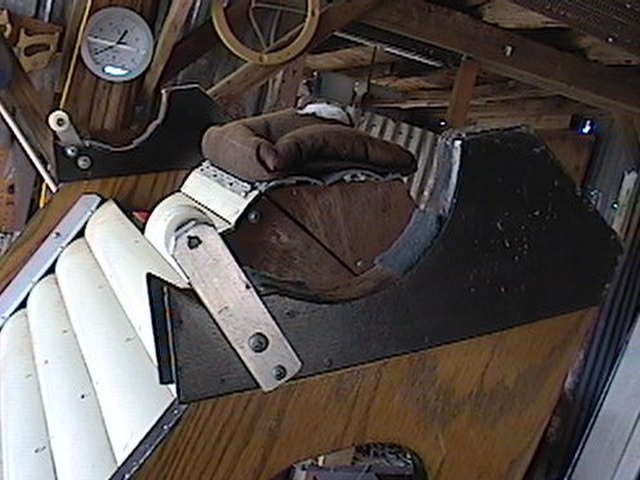 |
This view is of the
top of the chair section and shows the cradle for the OTA. Bearing surface is only felt pads here. The rollers
keep the OTA from sliding off the front, I think. Just in front of the rollers, you see a black material, hardboard,
that extends further in front and has a point facing upwards. One of these points is broken off and will be repaired.
Their funtion isn't known at this time, but once the OTA is again in the cradle, I'm sure their function will become
clear. EDIT: The function of the pointy hardboard was never discovered. Maybe aesthetic? (8/12/12) |
 |
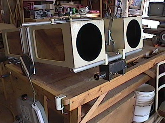
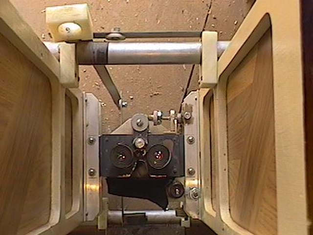
The OTA assembly from the business end. This picture is kind of busy, so it's hard to tell what's going on here. Answer: Mostly nothing. You can see the main mirrors and their associated secondaries mounted on single strips of aluminum inside the tubes. The front of the focusing mechanism is visible and its associated colimation screws, but not very clearly. Also, you can see the chrome tube in front, used for lifting the assembly on its bearings for access to the chair. the front brace holding the tubes together is also seen. EDIT: The secondary stalks and spider assemblies were collimated once and left. There was no ability to adjust collimation aside from brute force-bending, twisting or turning. The chrome tube is also a counterweight to move the center of mass of the assembly forward. (8/12/12) |
 |
This oblique view is slightly better. The entire left optical tube is seen, with the left side bearing and clip to accept the spring from the chair assembly. The center aluminum brace is seen ot top. The angled piece of aluminum stock between the tubes is the actuator for the headrest adjustment. Another example of mystery that should become obvious once the whole thing is assembled. |
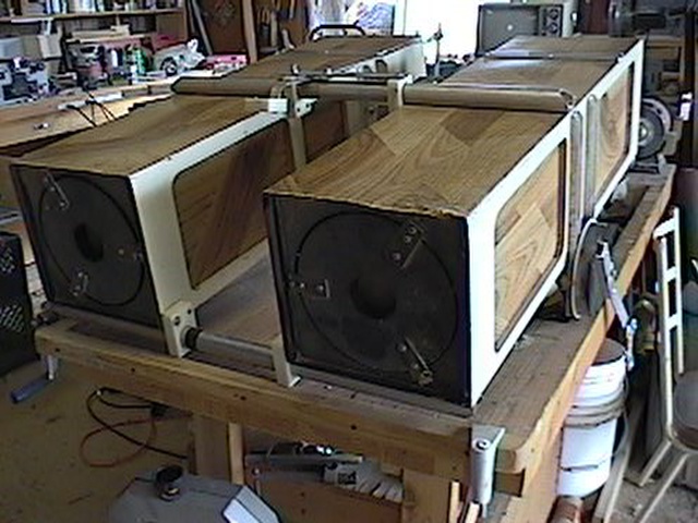 |
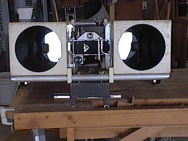
From the back, it looks like
about any small scope, except there's two of them. I really hope collimation isn't achieved using the mirror cell straps
seen at 3 points around the mirrors here. >eek< EDIT: Collimation was indeed achieved by shims placed under the mounting straps, as was typically Pierre. (8/12/12) |
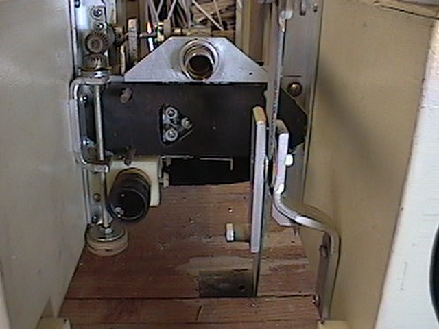 |
Here's a good view of
the focuser section from the front. The angled aluminum strip on the right is the headrest actuator. Lower left is the
focuser knob-a leather bushing held tight between a couple washers and mounted on a rod that rotates the gear on top.
A transversal gear meshes yet another gear that moves the whole shebang toward and away from the viewer. The hollow tube
seen at the top of this assembly is the sliding carriage for the eyepieces, not seen behind. EDIT: This entire section of the chair proved unmanageable and was totally redesigned. The functions of the screws and such were eventually discovered, but didn't work for a number of reasons, mostly interference with non-moving parts internally. (8/12/12) |
 |
I could have gotten slightly
closer on this one, but here goes anyway. EDIT: As mentioned, this entire assembly was redesigned, fabricated and installed on the redesigned version. (8/12/12)
|
 |
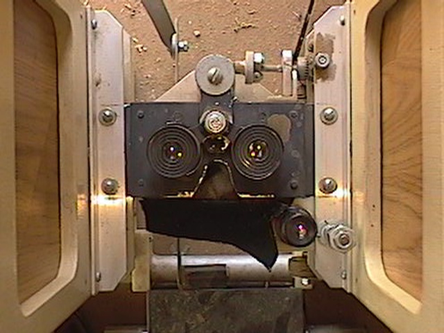
Ok, same view from farther back shows all of the above and the business end of the headrest adjustment lever. (Yeah, that square, plastic block with the round hole in it. Your guess is as good as mine...)
EDIT: The plastic block witht he whole in it slips over a piece of tubing attached to the old headrest. When the lever at the front is moved, it translates to an adjustment in the headrest, forward or backward. (8/12/12) |